
1. Introduction
Factory Acceptance Testing (FAT) is the final pre-shipment verification carried out at the equipment manufacturer's factory before the machine is packed and shipped.
For aerosol filling equipment, FAT should not be limited to checking whether the machine powers on. It should verify that the machine can run with the customer's actual cans, valves, filling volumes, and product requirements. A machine that cycles empty in an assembly bay does not prove it will function properly once pressurized propellants, liquid viscosities, and specific packaging tolerances interact on the production line.
At AILE, factory testing is built around practical, real-world operation:
- Requiring customers to provide sample cans, valves, and actuators or caps
- Requesting actual bulk material samples whenever special liquid behavior is involved
- Setting up and calibrating machine tooling to those physical samples
- Running the machine with actual materials before dispatch
- Recording clear video documentation of the entire cycle
- Confirming operating performance with the customer remotely
- Packing and crating only after full customer confirmation
2. What Should the Customer Send Before FAT?
Relying solely on technical drawings or data sheets creates unnecessary risks during commissioning. Even minor variances in can neck curvature, valve cup hardness, or gasket elasticity can change crimping and filling performance.
To conduct a meaningful aerosol filling line FAT, buyers should supply representative materials and clear operating targets:
- Aerosol cans representing every height and diameter ordered
- Valves matching the exact specification, including dip tube length and cup material
- Actuators and spray buttons
- Overcaps and protective closures
- Extension straws if the product design requires them
- Product material samples, especially for viscous, foaming, or shear-sensitive formulations
- Target liquid filling volume and acceptable tolerances
- Propellant type and target gas dosage per container
- Target can size spectrum requiring change parts
- Required continuous production speed
AILE normally recommends sending representative packaging materials for every size or configuration that will be used on the machine. While mechanical adjustments can theoretically be carried out on site, many customer operators lack the specialized experience required to align crimping jaws, gas injection heads, and container indexing guides. Having AILE calibrate each format at the factory, test it under power, and record the operating results prevents expensive troubleshooting delays after delivery.
3. FAT Step 1: Verify Machine Configuration
Before starting any functional cycles, confirm that the physical machine build strictly conforms to the agreed commercial and engineering terms.
Verify that:
- Machine model and physical orientation match the approved layout drawing
- Factory wiring, voltage, phase, and frequency match the destination facility power supply
- Mechanical stroke lengths and cylinder adjustments cover the complete height and volume range
- Valve sorters, crimping heads, and gassing nozzles match approved valve cup and stem dimensions
- Optional add-on modules, explosion-proof pneumatic components, or stainless steel contact upgrades are installed as specified
Confirm that the machine configuration matches the approved quotation, technical specification, and project requirements.
4. FAT Step 2: Test Actual Cans and Valves
Testing actual packaging materials is the most critical mechanical step in the FAT process. Theoretical calculations cannot anticipate physical container friction, valve insertion resistance, or container stability under indexing acceleration.
The mechanical evaluation must verify:
- Can feeding and starwheel positioning without jamming, surface scratching, or tipping
- Valve placement ensuring dip tubes insert smoothly without snagging on can rims
- Valve centering directly under the crimping head to eliminate tilted cups
- Crimping stroke engagement and tool release
- Can stability during high-speed indexing across all active stations
For one AILE semi-automatic aerosol configuration, typical crimping values may be around 27.1 to 27.3 mm in diameter and 5.0 to 5.2 mm in depth. Actual settings depend on the valve and machine configuration.
The customer's real cans and valves should be tested rather than relying only on drawings.
5. FAT Step 3: Verify Filling Performance
Aerosol filling involves both atmospheric or pressure-dosed liquid concentrates and pressurized propellant charging. Both phases require distinct verification criteria during FAT.
Liquid Filling Verification
Inspect the following items during the liquid dosing cycle:
- Smooth piston stroke or pump operation without product splashing or dripping onto container rims
- Target filling amount verified by net weight measurement
- Dosing repeatability across consecutive cycles
- Absence of fluid leakage around nozzle seals, check valves, and product manifolds
- Suitability for the specific material formulation, confirming smooth intake and discharge
One AILE semi-automatic configuration has a filling accuracy of approximately plus or minus 1 gram. Acceptance criteria should follow the selected machine model and approved technical specification.
Propellant Filling Verification
Verify the gas charging cycle across the following points:
- Gas filling operation through or around the valve stem without external venting
- Target gas charge verified by weighing containers before and after charging
- Pressure stability across the booster pump and accumulator during consecutive cycles
- Machine response time, ensuring rapid cylinder return without pressure drops
- Sealing condition immediately following gas injection, confirming internal valve seals close fully
6. FAT Step 4: Check Crimping and Sealing Result
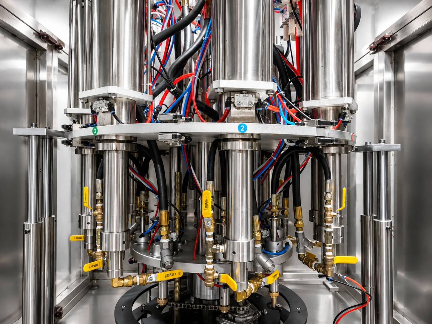
Crimping forms the permanent pressure barrier of the finished aerosol container. A dedicated mechanical inspection must verify the seal integrity across repeated samples.
The buyer should check:
- Crimping diameter across multiple points using a calibrated aerosol crimp gauge
- Crimping depth measured from the top rim of the valve cup to the crimp indent
- Valve alignment, ensuring stems sit vertically without angular deflection
- Absence of visible deformation, scoring, or buckling on the can neck and valve cup
- Zero leakage after filling, verified through water immersion or bubble testing
- Dimensional consistency across repeated test samples
A machine that runs smoothly but produces unstable crimping results should not be considered ready for shipment.
7. FAT Step 5: Run the Machine Continuously
FAT should include a continuous production run rather than only testing one or two cans. Testing single units often hides intermittent feed jams, thermal expansion in pneumatic systems, or gradual propellant pressure loss.
The continuous run must evaluate:
- Overall machine stability under steady production conditions
- Repeated feeding of containers without manual repositioning
- Absence of container jams at transition plates, guide rails, and starwheels
- Minimal operator intervention during standard operating cycles
- Station synchronization between liquid dosing, valve positioning, crimping, and propellant injection
- Absence of abnormal air leakage across pneumatic valves and manifolds
- Absence of abnormal vibration or mechanical noise in drive components
- Consistent finished output across the entire test batch
The test duration should be sufficient to reveal repeated-operation problems.
8. FAT Step 6: Check Optional Downstream Equipment
When a project includes an integrated Aerosol Filling Line or Standard Aerosol Filling Line, FAT should test the complete process ordered by the customer, not only the filling machine in isolation.
Inspect all connected downstream modules, including:
- Water bath leakage testing tanks, verifying smooth container immersion and transit
- Inline checkweighers, checking dynamic weighing accuracy and automatic reject gate timing
- Actuator presses, confirming nozzles seat securely without bending valve stems
- Overcap presses, verifying caps lock firmly without cracking plastic rims
- Coding and marking conveyors, ensuring smooth container transit past print heads
- Spray straw applicators, confirming precise feeding and insertion into actuator nozzles
- Interconnecting conveyors and turntables, checking smooth transfers without bottle tipping
9. FAT Step 7: Check Controls and Basic Operation
Control interfaces vary depending on whether the machine is a pneumatic semi-automatic unit or an automated system such as a Bag-on-Valve Filling Machine.
During FAT, verify:
- Start, stop, and pause functions responding cleanly without leaving containers stuck under active heads
- Emergency stop circuit immediately halting motion and venting or locking pneumatic pressure
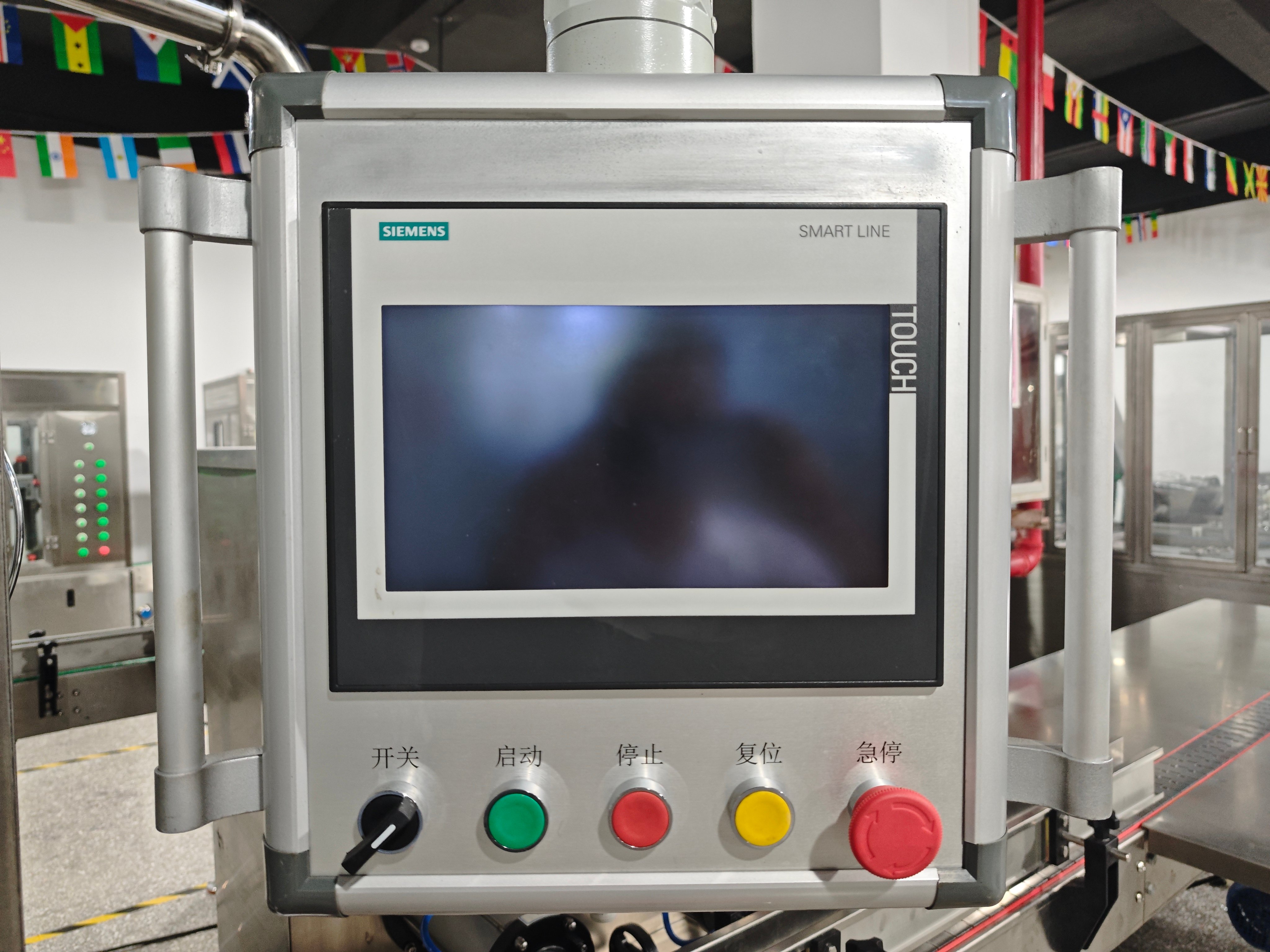
- PLC and touchscreen interface responsiveness on applicable automated models, including recipe selection and diagnostic screens
- Pneumatic pressure regulators holding steady operating pressures under load
- Safety interlocks and operational alarms triggering accurately
- Mechanical handwheels and height adjustment guides operating smoothly without binding
On select advanced automated systems, such as automated BOV lines, controls may incorporate a Siemens PLC paired with a touch screen, dedicated station controls for crimping and through-the-valve gas charging, and secondary liquid filling functions. Acceptance should confirm that all interface features function properly.
10. FAT Step 8: Record Video Evidence
Clear video evidence allows international buyers to inspect machine performance thoroughly without requiring international travel.
AILE normally records machine operation videos before packing so the customer can review the test result remotely.
A complete FAT video record should clearly document:
- Full machine overview showing overall construction, utility connections, and layout
- Material loading, container feeding, and guide rail transit
- Actual liquid filling cycles, showing nozzle stroke, cut-off action, and clean shut-off
- Valve placement and crimping action at close range
- Propellant filling operation on the dedicated Aerosol Propellant Filling Machine station
- Close-up inspection of finished cans, highlighting crimp quality and surface condition
- Synchronized operation of any optional downstream equipment included in the order
- Control interface screens, cycle indicators, and main pressure gauges
11. FAT Step 9: Customer Review Before Packing
After FAT, the customer should review the machine video, test results, and confirmed configuration before final packing.
The operational workflow follows a clear, disciplined sequence:
- Factory Acceptance Testing executed with actual customer samples
- Comprehensive video recording and parameter logging
- Customer review and technical confirmation
- Final mechanical adjustments if required by the customer
- Anti-rust protection, film wrapping, and solid crate packing
- Export dispatch and shipment
This structured review ensures that any necessary fine-tuning happens in the manufacturing workshop rather than during on-site commissioning.
12. What FAT Does NOT Mean
Understanding the practical boundary of a Factory Acceptance Test prevents misunderstandings regarding site commissioning and regulatory responsibilities.
FAT does not replace:
- Formal CE or ATEX regulatory certifications, which require dedicated compliance documentation
- Local municipal permits, environmental authorizations, or fire safety approvals for hazardous chemical storage
- Installation Qualification (IQ) and Operational Qualification (OQ) protocols executed in the buyer's plant
- Site Acceptance Testing (SAT), which verifies line performance when connected to permanent factory utilities and bulk gas supplies
- Industrial production licenses required to manufacture commercial aerosol products
FAT confirms that the equipment has been tested against the agreed project requirements before shipment. It does not replace local regulatory approval or site acceptance after installation.
13. Buyer FAT Checklist
Use this structured reference table to verify critical inspection checkpoints before authorizing dispatch:
| FAT Item | What to Check |
|---|---|
| Machine Configuration | Confirm model, voltage, frequency, ordered options, and dimensions match technical specifications. |
| Packaging Compatibility | Verify smooth feeding and handling of actual cans, valves, actuators, caps, and straws. |
| Liquid Filling | Check dosing volume, nozzle cut-off action, fluid dripping, and repeatability across cycles. |
| Propellant Filling | Verify gas filling operation, gas charge volume, booster pressure stability, and valve seal closure. |
| Crimping and Sealing | Measure crimp diameter, crimp depth, stem verticality, and absence of container neck damage. |
| Continuous Run | Run multiple cans continuously to confirm repeated feeding, starwheel indexing, and zero jamming. |
| Controls and Safety | Test start, stop, emergency stop, air pressure regulators, and touchscreen controls if applicable. |
| Downstream Equipment | Verify leak testing tanks, checkweighers, cap presses, and conveyors run in coordination. |
| Finished Samples | Check visual finish, crimp profile, container integrity, and spray button actuation. |
| Video Documentation | Review comprehensive testing videos covering the full line, individual stations, and finished units. |
| Pre-Packing Condition | Verify fluid lines are drained, bare metal surfaces are protected, and machine is prepared for crating. |
14. Next Steps for Your Project
Send AILE your cans, valves, product information, and target filling requirements before production. We can use your actual materials for pre-shipment machine testing and provide FAT videos for review before packing. Whether configuring a high-speed Lubricant Aerosol Filling Line or a specialized Bag-on-Valve Aerosol Filling Line, testing physical packaging components upfront ensures reliable operation from day one.