
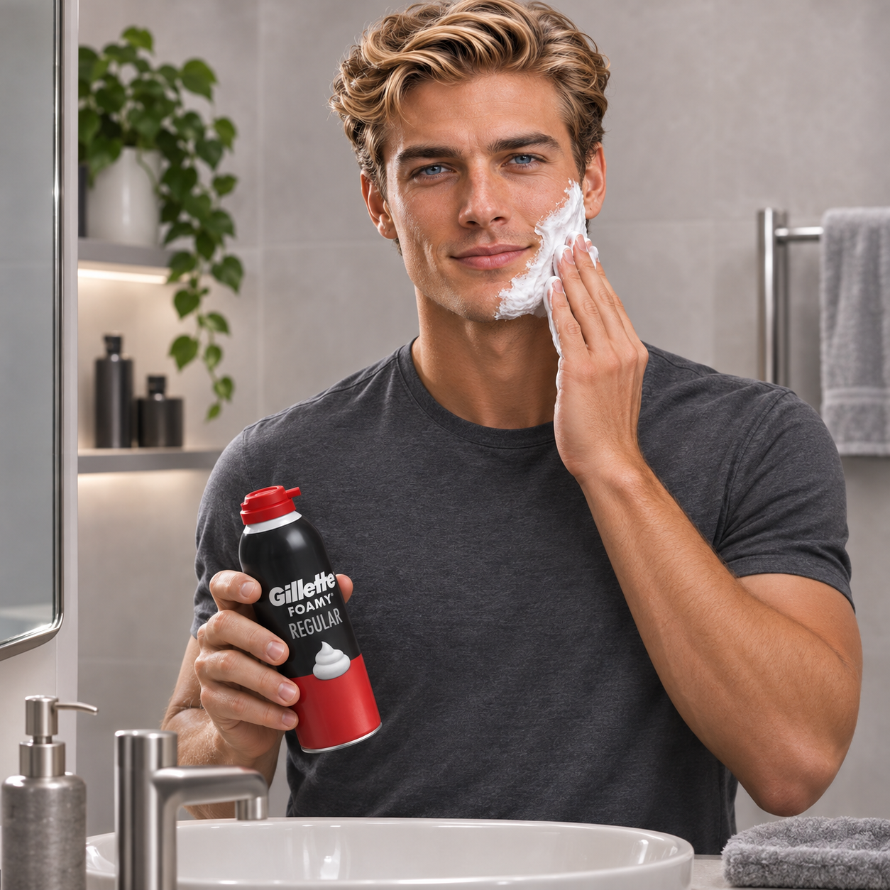
A shaving foam aerosol filling line is an integrated packaging system designed to batch, dose, seal, and pressurize shaving cream into aerosol cans. The complete process encompasses raw formulation preparation, volumetric liquid filling, valve placing, crimping, propellant charging, and downstream finishing.
Chapter 1: What Is a Shaving Foam Aerosol Filling Line?
A shaving foam aerosol filling line is a complete engineering setup that converts bulk cosmetic formulation into a pressurized, ready-to-dispense consumer aerosol can. Unlike dry powder or simple liquid packaging lines, shaving foam production requires seamless integration between chemical preparation and gas filling operations.
The complete manufacturing workflow operates across two coordinated phases:
- Product Preparation & Storage: Water, fatty acids, surfactants, and conditioning agents are blended, heated, and saponified in an upstream mixing vessel before transfer to holding tanks.
- Liquid Product Dosing: The liquid base is volumetrically dosed into clean, empty aerosol cans via an automatic or semi-automatic shaving foam aerosol filling machine.
- Valve Placing and Crimping: Precision 1-inch aerosol valves are positioned onto the can openings and mechanically crimped to establish a pressure-tight seal.
- Propellant Gas Charging: High-pressure metering heads inject liquefied propellant (such as LPG or DME blends) straight through the crimped valve stem.
- Actuator Insertion & Overcapping: Dispensing nozzles and protective caps are pressed into position.
- Downstream Quality Inspection: Cans pass through automated checkweighers, hot-water bath leak detectors, and date-coding stations.
Investing in a balanced shaving foam production line prevents bottlenecks between bulk batch preparation and high-speed packaging stations.
Chapter 2: Why Shaving Foam Requires a Dedicated Filling Configuration
Shaving foam packaging differs from standard liquids because the product is an emulsion that changes physical properties under shear and only generates its final foam structure when released into atmospheric pressure.
2.1 Formulation Characteristics and Viscosity Dynamics
A shaving cream formulation behaves differently than low-viscosity deodorants or body sprays. The concentrated soap/emulsion base contains surfactants, lubricants, and humectants that make it prone to mechanical foaming if handled improperly inside filling nozzles.
Nozzle port diameters, piston stroke speeds, and cutoff stroke damping must be tailored around your fluid rheology:
- High-shear piston strokes can prematurely aerate the base during filling.
- Drip nozzles cause product residue on the can neck, interfering with valve crimp integrity.
- Viscosity variations across batch temperatures require positive-displacement metering cylinders with adjustable intake/discharge timing.
2.2 Product Preparation: Emulsification vs. Agitation
Depending on your formula, product preparation demands specific shear conditions. Formulations utilizing stearic or myristic acids neutralized with triethanolamine (TEA) require high-temperature saponification and thorough homogenization to prevent phase separation during long shelf storage.
Other simplified or concentrated formulas only need uniform paddle agitation and controlled heating. At AILE, we verify whether your base requires high-shear rotor-stator processing or standard jacketed blending before specifying upstream tanks.
2.3 Filling Stability and Dispense Performance
A stable, creamy lather depends on four synchronized parameters: liquid fill volume, valve/stem orifice dimensions, propellant mass, and interior equilibrium pressure. Inconsistent liquid dosing shifts the gas-to-liquid ratio, yielding watery discharge or sputtering gas pockets.
A reliable line must deliver repeatable volumetric accuracy across liquid dosing and gas metering heads.
Chapter 3: Step 1 — Product Preparation and Mixing System
The quality of the extruded shaving lather depends on emulsion stability established during the mixing stage. Raw materials must be fully dispersed and stable before entering the filling buffer tank.
Process Breakdown
- Raw Material Compounding: Deionized water, glycols, and active lubricants are charged into the primary tank while solid fatty acids melt at controlled temperatures (typically 70°C to 80°C).
- Alkaline Neutralization: Neutralizing agents are metered to drive saponification under continuous, low-vortex agitation.
- Emulsification & Homogenization: For formulations prone to air entrapment or separation, blending under vacuum prevents ambient aeration, creating a dense, micro-droplet emulsion base.
- Controlled Product Transfer: The completed base pumps into jacketed buffer vessels to hold stable working temperatures and prevent viscosity spikes before reaching the packaging line.
For formulations requiring fine droplet dispersion, explore our specialized Vacuum Emulsifying Mixers engineered with sanitary SUS316L contact surfaces and variable-speed homogenizing heads.
Chapter 4: Step 2 — Liquid Product Dosing
Liquid dosing introduces a metered volume of shaving foam base into empty tinplate or aluminum aerosol cans without neck splashing or premature foaming.
Operational Considerations
- Nozzle Architecture: AILE integrates pneumatically driven diving nozzles that descend near the base of the container, rising gradually with the liquid level (bottom-up filling) to prevent aeration.
- Positive-Cutoff Valve Seals: High-viscosity emulsions demand positive suck-back or mechanical pin-seal nozzles to eliminate dripping onto the can curl.
- Dosing Tolerances: Industrial piston cylinders machined from SUS316L deliver dosing accuracy within ±1% across standard commercial volumes (50 ml travel sizes up to 400 ml family formats).
For low-to-medium throughput lines or initial regional production trials, explore our flexible Semi-Automatic Aerosol Filling Machine configurations.
Chapter 5: Step 3 — Valve Placement and Crimping Process
Aerosol crimping expands the metallic skirt of a 1-inch valve cup outward into the container neck curl, forming a hermetic, pressure-retaining mechanical joint.
Critical Crimp Settings
Crimping must securely contain the internal working pressure without pinching the valve gasket or deforming the can shoulder. Collet segment alignment and expansion stroke depth determine mechanical seal integrity:
- Collet Precision: Segmented crimping jaws expand uniformly across 360 degrees to prevent ovalization of the mounting cup.
- Package-Specific Adjustment: On an AILE semi-automatic testing configuration, typical baseline crimp values range around 27.1–27.3 mm in diameter and 5.0–5.2 mm in depth. Actual dimensions must be matched against the specific valve plate gauge, gasket durometer (Buna-N, Neoprene, or Butyl), and can curl profile.
- Pre-Shipment Proofing: Tooling jaws are custom-machined and dimensionally verified using customer-supplied cans and valves before machinery leaves the factory floor.
Chapter 6: Step 4 — Propellant Gas Filling
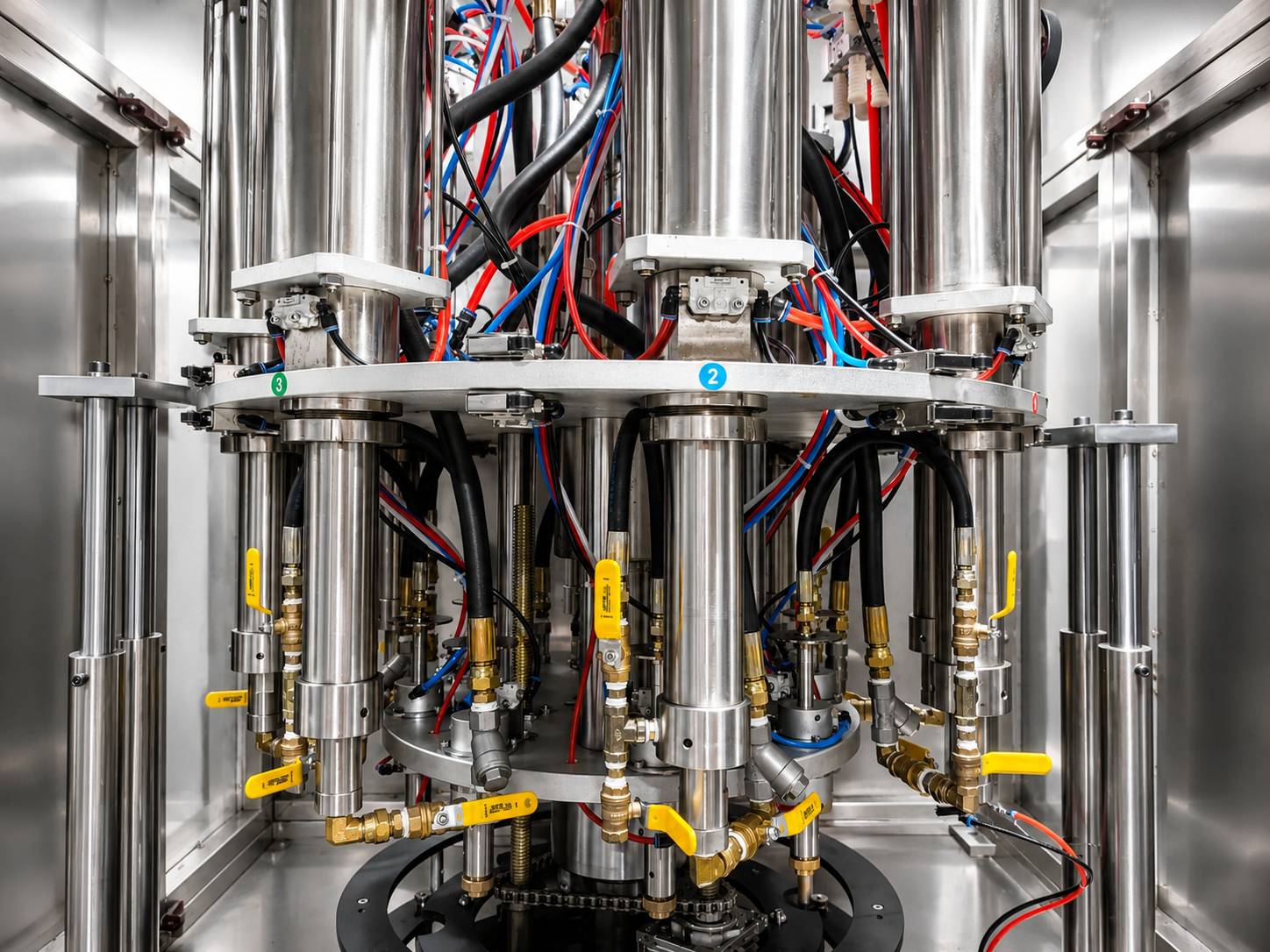
Propellant charging injects liquefied gas into the sealed container under high hydraulic pressure, through the central valve stem or around the valve grommet.
Liquid propellants act as both the driving pressure source and the primary expansion agent. As the formula exits the actuator into ambient atmospheric pressure, the dissolved propellant vaporizes instantly, transforming the liquid film into a micro-cellular lather.
Gas Types and Equipment Compatibility
- Liquefied Hydrocarbons (LPG): Blends of propane, isobutane, and n-butane (such as A-31 or A-46) remain the worldwide cosmetic industry standard for shaving foam. They provide steady internal pressures and mix cleanly with soap bases.
- Dimethylether (DME): Offers water solubility, making it an option for specific low-VOC or hybrid cosmetic formulations.
- Safety Construction: Hydrocarbon-compatible gas heads feature explosion-proof pneumatic logic, grounded anti-static POM conveyor chains, and enclosed gas booster pumps.
For dedicated propellant injection stations, review our Semi-Automatic Aerosol Propellant Gas Filling Machine. For an in-depth breakdown of gas characteristics, read our guide on LPG vs. DME vs. N2 vs. CO2 Aerosol Propellants.
Chapter 7: Step 5 — Actuator, Cap, and Finished Foam Performance
A stable aerosol packaging line produces consistent internal weight and pressure, but the final foam volume, spreadability, and bubble density are determined by the interaction between the product formula, propellant concentration, valve internal orifices, and actuator nozzle geometry.
Factory Experience: The same aerosol filling machine, operating with identical liquid volume and propellant mass, can yield two entirely different results if the actuator mechanical break-up unit (MBU) or valve expansion orifice changes.
Factors Influencing Foam Texture
- Internal Valve Orifice (Vapor Tap & Stem): Dictates how fast the liquid emulsion mixes with gas during actuation.
- Actuator Orifice & Discharge Nozzle: Wide-mouth spouts with direct paths generate thick shaving ribbons, whereas fine mechanical break-up inserts risk excessive shear or early dripping.
- Temperature Stability: Final dispense velocity shifts if the internal vapor pressure drops in cold storage.
Because valve and actuator compatibility directly dictates consumer experience, AILE recommends submitting real containers, functional valves, and production-grade actuators during the initial machinery sizing stage.
Chapter 8: Semi-Automatic vs. Automatic Shaving Foam Filling Line
Choosing the right machine configuration requires balancing immediate capital expenditure with labor availability, batch size variability, and annual output targets.
| Configuration | Typical AILE Capacity | Operator Requirement | Footprint (Approx.) | Best Suited For |
|---|---|---|---|---|
| Semi-Automatic (Bench / Stand-alone) | 500–700 BPH | 2–3 Operators | 2 × 3 m | Pilot facilities, regional contract packaging, frequent formula/can changeovers |
| Standard Automatic Line | 2,400–3,600 BPH | 1–2 Operators | 12 × 2.5 m | Medium commercial production, dedicated can diameters, continuous daily output |
| High-Speed Rotary System | 4,800–7,200 CPH | 1 Operator (Supervisory) | 20 × 4 m | Large consumer brands, round-the-clock packaging, single-SKU mass manufacturing |
Selection Criteria
- Batch Size & SKU Flexibility: If your brand runs multiple private-label brands with frequent can diameter shifts (e.g., switching between 45 mm, 52 mm, and 65 mm cans), a semi-automatic station or modular linear indexing line minimizes changeover downtime.
- Automation Degree: Standard automatic lines integrate starwheel indexing, automatic can feed tables, and automated valve placers, reducing manual container handling to raw material staging.
- Workshop Infrastructure: High-speed propellant rooms require dedicated explosion-proof exhaust, gas detection arrays, and outdoor propellant storage tanks.
Compare production capabilities via our Standard Aerosol Filling Line specifications or evaluate complete plant setups across our Aerosol Filling Lines portfolio.
Chapter 9: Recommended Shaving Foam Production Line Setup
A complete manufacturing line combines core filling stations with downstream quality and secondary packaging equipment. Below is a structured machinery breakdown:
Core Machinery
- Jacketed Blending Vessel / Emulsifier: Heated stainless steel tanks (SUS316L contact parts) equipped with agitators and optional homogenizers.
- Positive-Displacement Liquid Filling Machine: Multi-head diving nozzles with calibrated metering cylinders.
- Aerosol Valve Placer & Clincher: Manual or automatic 1-inch valve sorter with mechanical crimping jaws.
- Propellant Charging Machine: High-pressure piston dosing pumps with reinforced gas heads.
- Conveyor & Indexing System: Anti-static POM plastic slat conveyors with pneumatic safety starwheels.
Downstream Packaging & Quality Stations (Configured Per Project)
- Automatic Water Bath Leak Tester: Submerges pressurized cans into 50°C water to detect pinhole leaks or valve seal failures per safety standards.
- Dynamic Checkweigher: Rejects cans deviating from target liquid or gas fill weights.
- Automatic Actuator Button Presser: Automatically orientates and presses dispensing nozzles onto valve stems.
- Aerosol Can Overcapper: Feeds and presses dust caps onto finished cans.
- Batch Coding Machine: Continuous Inkjet (CIJ) or laser coder printing lot codes and expiry dates on concave can bottoms.
- Carton Packing Station: Semi-automatic case packers or shrink-wrapping tunnels.

Chapter 10: Technical RFQ Checklist: What Information to Provide
To receive a fast and accurate machinery quotation from an equipment manufacturer, provide detailed specifications about your intended package, chemistry, and factory floor conditions.
Before contacting engineering, prepare the following parameters:
- Product Formulation Type: Standard shaving foam, sensitive gel, or menthol cooling base
- Base Viscosity / Behavior: Estimated cP (centipoise) at filling temperature and foaming tendencies
- Can Dimensions: Material (tinplate or aluminum), body diameter (mm), total height (mm)
- Target Liquid Fill Volume: Specified in milliliters (ml) or grams (g)
- Propellant Media: LPG (Propane/Butane), DME, or custom hydrocarbon blend
- Valve & Actuator Specs: 1-inch mounting cup profile, gasket compound, actuator nozzle style
- Target Production Output: Required containers per hour (BPH) or shift volume
- Electrical & Utilities: Factory voltage/frequency (e.g., 380V 50Hz 3-phase) and air compressor capacity
- Downstream Scope: Required level of inspection (water bath, checkweigher, boxing)
Refer to our complete Aerosol Filling Machine RFQ Checklist for a downloadable parameter worksheet.
Chapter 11: Factory Acceptance and Pre-Shipment Sample Testing
Factory Acceptance Testing (FAT) validates that your filling line achieves specified dosing tolerances, mechanical crimp depth, and cycle speeds using your exact packaging materials.
The AILE Pre-Shipment Validation Protocol
- Tooling Customization: Custom-machined starwheels, pucks, crimp collets, and gas adapters are fabricated to fit your container samples.
- Material Compatibility: Gasket materials and cylinder seals are inspected against your formulation's active components to prevent swelling or degradation.
- Continuous Dry & Wet Run: The machine executes continuous mechanical dry-runs followed by actual wet-fill testing with dummy product or customer-supplied bulk material.
- Crimp Inspection: Crimp diameter and depth are verified across sample runs with precision micrometers.
- Video Inspection Dossier: Detailed operational video footage and dimensional inspection reports are shared for customer sign-off prior to wooden crate packing.
Review standard acceptance criteria in our Aerosol Filling Line FAT Checklist.
Chapter 12: Frequently Asked Questions (FAQ)
What machine is used to fill shaving foam?
A complete shaving foam packaging setup requires an upstream mixing or emulsifying vessel, an aerosol liquid filling machine (utilizing diving nozzles), a 1-inch valve crimper, and an explosion-proof propellant gas filling machine.
Does shaving foam require a mixing tank or a vacuum emulsifier?
Equipment requirements depend on your formulation. Classic formulas using melted stearic acid neutralized with TEA benefit from vacuum emulsification to produce a fine, un-aerated emulsion. Simpler cold-blend or pre-neutralized bases only require a standard jacketed stainless steel mixing tank with paddle agitation.
Can one aerosol filling line handle different shaving foam can sizes?
Yes. Industrial aerosol lines accommodate different container heights and diameters. Adjusting the line for height involves manual or motorized head height positioning, while changing can diameters requires swapping starwheel pockets, can guides, and conveyor railing widths.
What propellant is used for shaving foam aerosols?
Liquefied Petroleum Gas (LPG)—typically a purified propane and butane blend—is the most common propellant worldwide due to its cost efficiency and ideal vapor pressure curves. Dimethyl ether (DME) is also used for specific alcohol- or water-soluble formulations. The chosen gas determines machine booster pump ratings and safety exhaust configurations.